Installing the hardware
Jun 8, 2024
m73
lenovo
homelab
kubernetes
hardware
mpcie
ethernet
Putting together a homelab Kubernetes cluster in my own stubborn way. I’m assuming a reader who’s basically me before I embarked on this little expedition, so I won’t go into minute detail about day-to-day Linux setup and administration - only the things that are new to me and have changed since I last encountered them.
- Part 0 - Best laid plans
- Part 1 - Installing the hardware
- Part 2 - Boot across the network
- Part 3 - PXE Booting Debian with an NFS Root Filesystem
- Part 4 - Filesystems for everybody!
- Part 5 - Getting a clean boot
- Part 6 - Kubernetes at last
Sections added as I actually proceed with this!
Missing Hardware
Ok, well, one thing I forgot when I ordered those PCs was… they didn’t come with power supplies either. Oops. They also don’t take any kind of standard barrel connector! Instead they want a funny little rectangular Lenovo-specific thing.
Did I have any spare? I did not… but my mpcie Ethernet card hadn’t turned up yet, so there was no desperate hurry. I bid upon some on Tradera, the Swedish equivalent of eBay (so that the postage wouldn’t be too bad) and even found a largeish batch of mixed power adapters that included a few and went for a song. Better yet, you can get a cheap converter from a standard barrel jack to the Lenovo connector, so I have some of those on order.
By the time my Ethernet adapter turned up I had enough to get started at least!
What’s in the box?
So what do I actually have here? Here’s a photo of the front fascia:
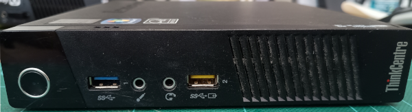
Front of the Lenovo m73 Tiny
And here’s a photo of the back panel:
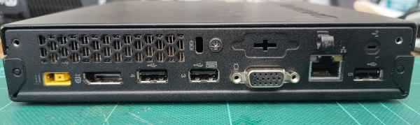
Back of the Lenovo m73 Tiny
It’s really quite a nicely equipped machine. There’s a Display Port connector and a VGA connector - I was faintly surprised that it had Display Port rather than HDMI, but it’s a bit academic to me as I’ll be using all these machines headless except for initial setup purposes.
Five USB ports, a couple of audio connectors (as well as an internal speaker), and an RJ45 socket for wired gigabit Ethernet rounds off the external stuff. Note also the blanking plate mentioned in the planning section because I’ll be using that for the second Ethernet port later.
Inside there’s the mpcie connector that would have been used for WiFi cards (none of mine were equipped with one), and on the back panel top-right you can see where its antenna would have been fixed to the case. There’s a standard SATA connector for an internal drive, and finally there are two SODIMM slots for RAM; as provided there were 4G RAM installed in each machine.
The mechanical upgrade
Once I’d booted each machine to make sure they were working - or at least working well enough to get into the BIOS setup screen system summary the RAM upgrade was pretty swift. Open up each machine, remove the 4G memory stick, blast the slots with compressed air to clean out any dust, add two 8G SODIMMs in the empty slots, check again that it could boot to the BIOS summary page, and verify that it was showing 16G of RAM installed instead of 4G.
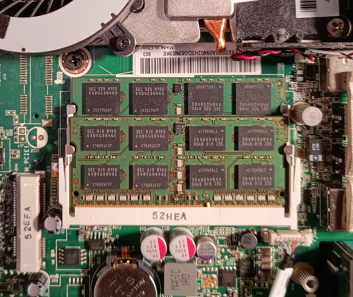
The upgraded 16GB of DDR3 1600MHz RAM
I started with 16 of the 8G SODIMMs, so Once I ran out of those, for the last two machines I switched to just adding one of the small pile of spare 4G SODIMMs instead. One of the machines started out with 2x4&B instead of 1x4GB for some reason, so I had 7 spare sticks of RAM. Not sure I’ll ever find a use for them, but you never know!
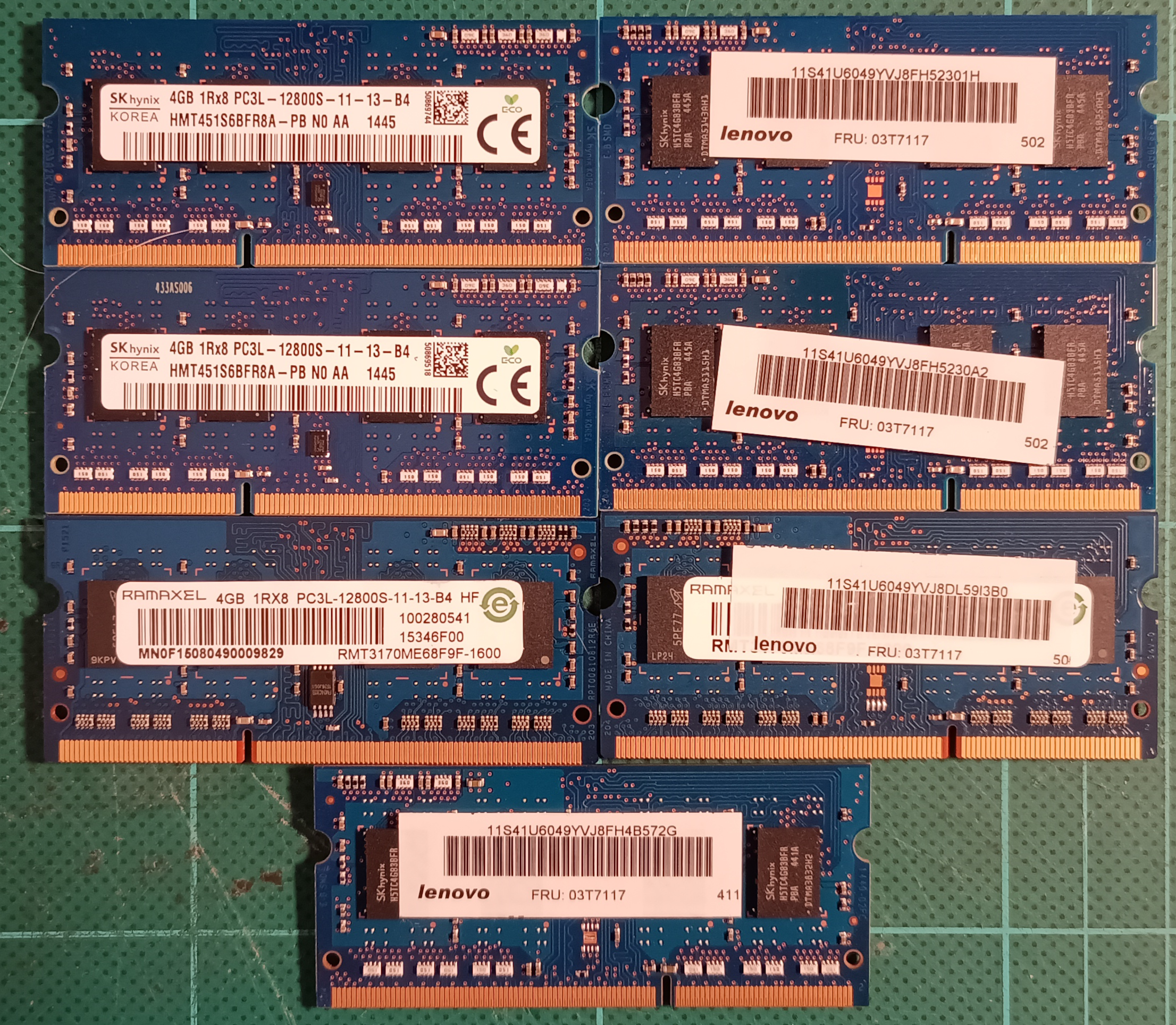
Seven DDR3 4GB SODIMMs
I had zero problems with the RAM upgrades.
Incidentally, I think it would be possible to put two 16G SODIMMs into the slots and give it 32G total - but 16G DD3 SODIMMs are about £100 each, and that’s a more expensive upgrade than these little machines merit. For now anyway.
Forewarned is forearmed - adding the second ethernet adapter
Before I started on this exercise I’d found this excellent thread on Reddit from someone also wanting to add a second ethernet port ¹ for similar purposes. The good news is that they succeeded, albeit with a rather ugly 3D printed mount hanging off the back of their machine. The bad news is that there are BIOS issues - specifically the machine only allows devices from a whitelist to work. But there is a workaround that I can try if I have the same problem.
Nothing ventured, nothing gained, though, so I set to. My first alarm was that the mpcie adapter I’d bought was too large for the (half-length mpcie) space available! Happily I almost immediately realised that half the card was discardable - purely structural with a perforation allowing it to be removed.
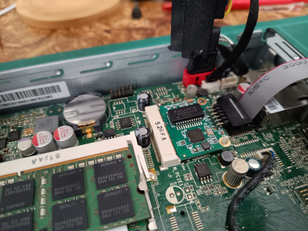
Oh thank god it fits
Refitted, I booted the machine up to this:
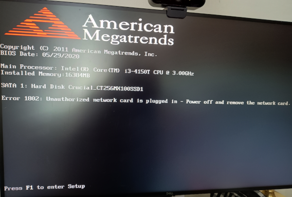
Computer says no.
Yep, that Error 1802: Unauthorized network card is plugged in - Power off and remove the network card. message
looks awfully familiar from the Reddit post. This screenshot was taken at an intermediate point when I had temporarily
installed the SATA SSD drive and in fact I had no trouble with that drive at all.
I had confidence in that Reddit thread, so I removed that small blanking plate from the back of the machine (with the aid of an old philips screwdriver and a small hammer) and installed the RJ45 socket into the empty space. Happily it fitted rather nicely into that D-Sub sized space:
An RJ45 socket where once was a blanking plate
I was relieved that it fitted so well and checked that I could plug and remove a network cable without any problem. So for getting the network up and running, let’s see if the advice in that Reddit thread worked.
BIOS I will fight you
In short that advice was: that there’s a complicated way to update the whitelist on the m73 Tiny’s BIOS, or if
you’re not too choosy you can also update the machine’s serial number and type code to read INVALID and it will
object slightly but nonetheless accept the card. I am not too choosy.
It was all a bit fiddly, so I’ll cut to the chase - it worked, the machine beeps twice and still puts up the complaining message, but that message can be ignored, and it will continue to start up with the ethernet card recognised and working.
So … how do you do this? Uh, you still need to use the BIOS update tools and the instructions on the Lenovo website are less than clear on how to do this when you’re not already in Windows or something. But they do have the necessary files on their downloads page.
I had no luck with the very latest version (4th January 2022) of the BIOS - I could upgrade to it, but the “INVALID” fields didn’t achieve anything. However on the preceding version from 24th June 2021 (see “Previous Version” section on that page) it worked ok. So given those files, and omitting some of my mis-steps, here’s what I did:
I downloaded and unzipped the Free DOS Lite image
(an open source MS DOS compatible OS). I then used Startup Disk Creator
on my Ubuntu laptop to make a bootable USB drive containing Free DOS. I unpacked the
file fhjt86usa.zip from Lenovo and copied
everything from it except for AUTOEXEC.BAT onto that USB drive.
I then used that thumb drive to boot the Lenovo into DOS. From here the following command updates the BIOS:
flash2 /mtm:INVALID /sn:INVALID imagefh.rom
That sets the “machine type” and the serial number to “INVALID” - it does need to be in upper-case - and flashes the updated BIOS from the ROM file.
The flags are documented towards the end of the Lenovo download page (linked above) or they’re also in a text file
available as fhjt86usa.txt from the same location.
There’s the intriguing possibility mentioned in that file of changing the boot logo… and I did have a play with that. However, the maximum size for that file logo is rather small (7k) and I couldn’t create anything worth using that was small enough. Given that these boxes are going to run headless once they’re working I didn’t pursue it. Maybe one day.
BIOS Gotchas
Aside from needing to have that ‘INVALID’ setting in upper-case, and needing to be on a specific version, not the latest, of the BIOS update, there were a few other things that went wrong:
I had the cable from the mpcie network card to the ethernet port the wrong way around. D’oh. This one really stressed
me out - the symptom was that I could boot all the way into Debian, and see the card when I issued the lspci
instruction, but when I plugged a network cable in the activity lights didn’t flicker, and Linux (correctly) thought
there was no network connection on the card. When I eventually realised what I’d done everything just magically
started appearing.
I also had an issue where the “Wireless LAN” option in the BIOS was set to disabled and this in turn disabled the mpcie socket as that’s where the wifi card would normally be installed! One to check if you have problems.
BIOS settings and verifying the hardware
Here’s what the boot screen looks like when everything’s updated:
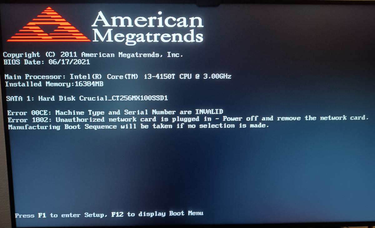
Boot up with the BIOS update
Note that although it’s still whining about the installed network card, now it also says:
Manufacturing Boot Sequence will be taken if no selection is made.
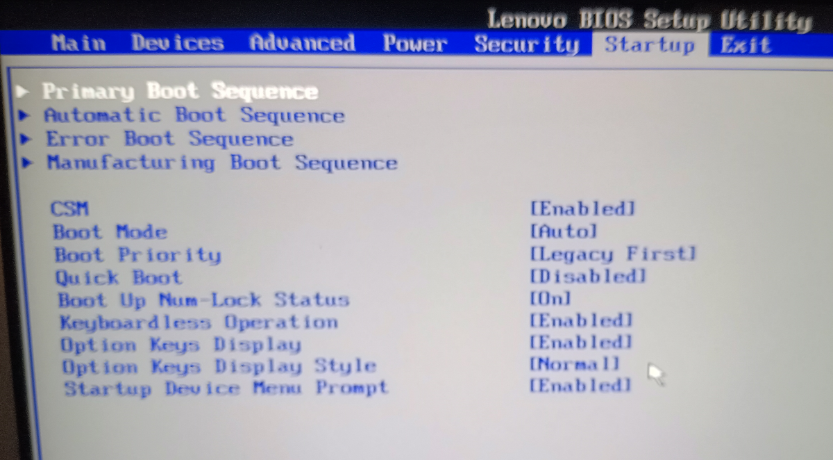
When you hit F1 to go into the BIOS setup page, this is how it looks:
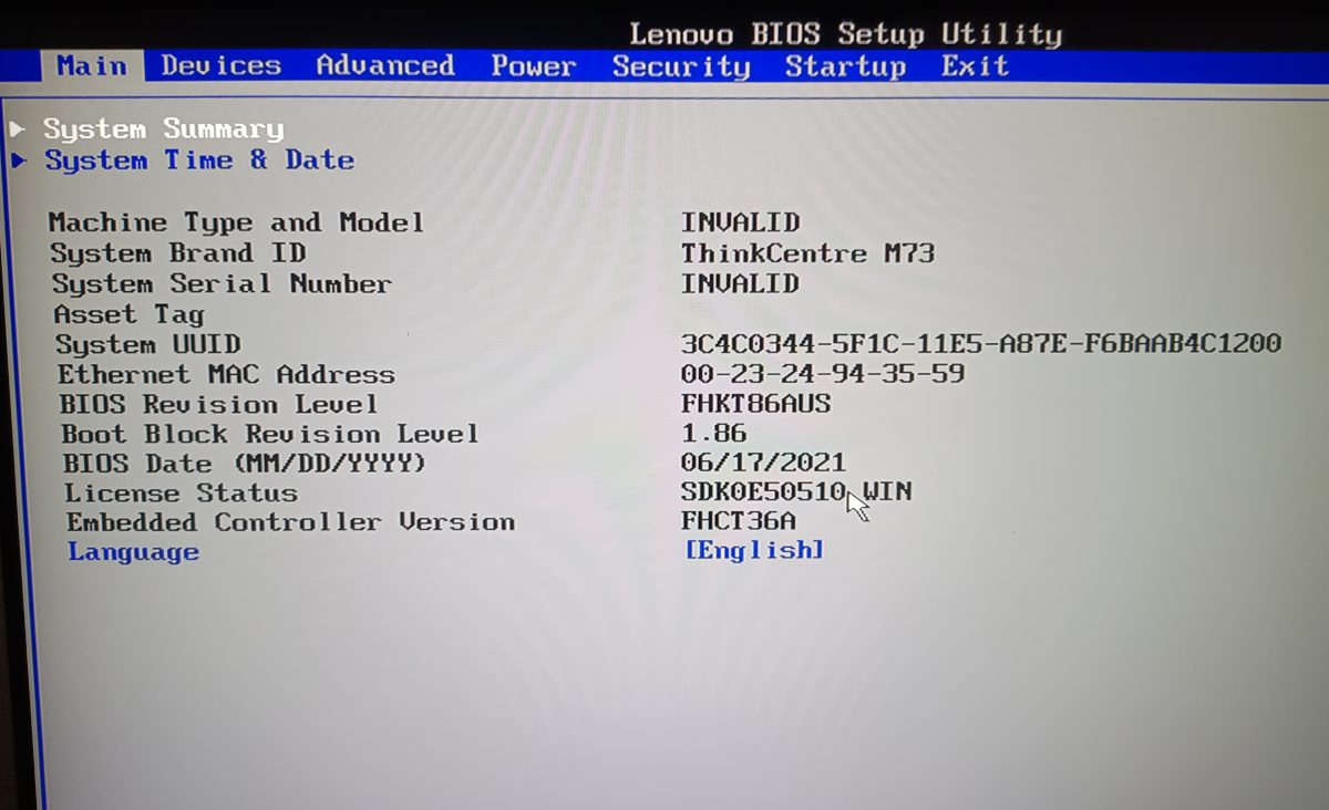
Setup screen with the BIOS update
Here you can see the magic values I overrode along with the BIOS update:
Machine Type and Model: INVALID
...
System Serial Number: INVALID
...
You can also see that the actual BIOS release date was 17th June 2021, so presumably the date on the Lenovo website (the 24th) is when it was released to the public.
That mention of the Manufacturing Boot Sequence on the boot screen is quite accurate - but you can change the contents of this in the BIOS on the “Startup” page.
Startup selected in the BIOS setup (sorry about the blur)
Cursoring down to the Manufacturing Boot Sequence you can then see on the following screen how I set things up:
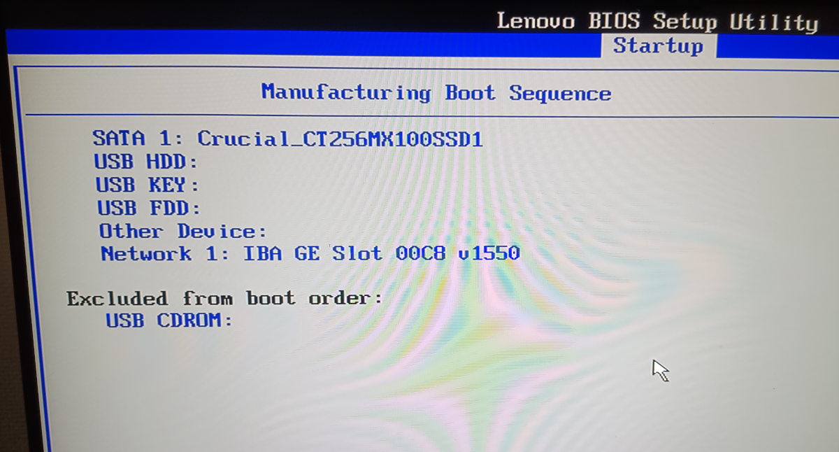
Viewing the Manufacturing Boot Sequence
As you can see, this boot sequence will boot from the SATA drive first, then USB drives (at the point this photo was taken I’d already installed the SATA drive, so you can see it’s details specified here).
I changed a few other BIOS settings while I was messing with these things:
- Turned on Compatibility Support Mode (CSM)
- Set Boot Mode to “Auto”
- Set Boot Priority to “Legacy First”
- Enabled “Keyboardless Operation” (important as these are going to run completely headless)
Some of the following changes were made before I installed the mpcie Ethernet card, so if you’re having trouble with that, double check them!
- On the Security page I set Allow Flashing BIOS to a Previous Version to “Yes”
- On the Advanced page I set Intel (R) Virtualization Technology to “Enabled”
- On the Devices page I made sure that
- Onboard Ethernet Controller was “Enabled”
- Boot Agent was set to “PXE”
- Wireless LAN was set to “Enabled” (I think this actually enables the epcie slot in which case it’s absolutely necessary!)
Connecting wires and verifying boot!
With the cluster gateway machine fully beefed up and an empty 512GB SATA drive installed in it along with the extra memory and the extra network port, I had the basics of the cluster gateway on my network. I showed in Part 0 the logical plan for the network - here’s the more-or-less physical plan:
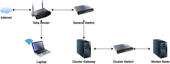
The physical networking
I’d picked up a 16 port Gigabit switch, the D-Link DGS-1016D for a song to be the switch for the subnet, so the next step as shown in the diagram above, was to plug one port of the new machine into the existing Telia Router (or rather another existing switch attached to that), and the other into the new switch. That is - one to connect on the internet side and the other on the cluster side.
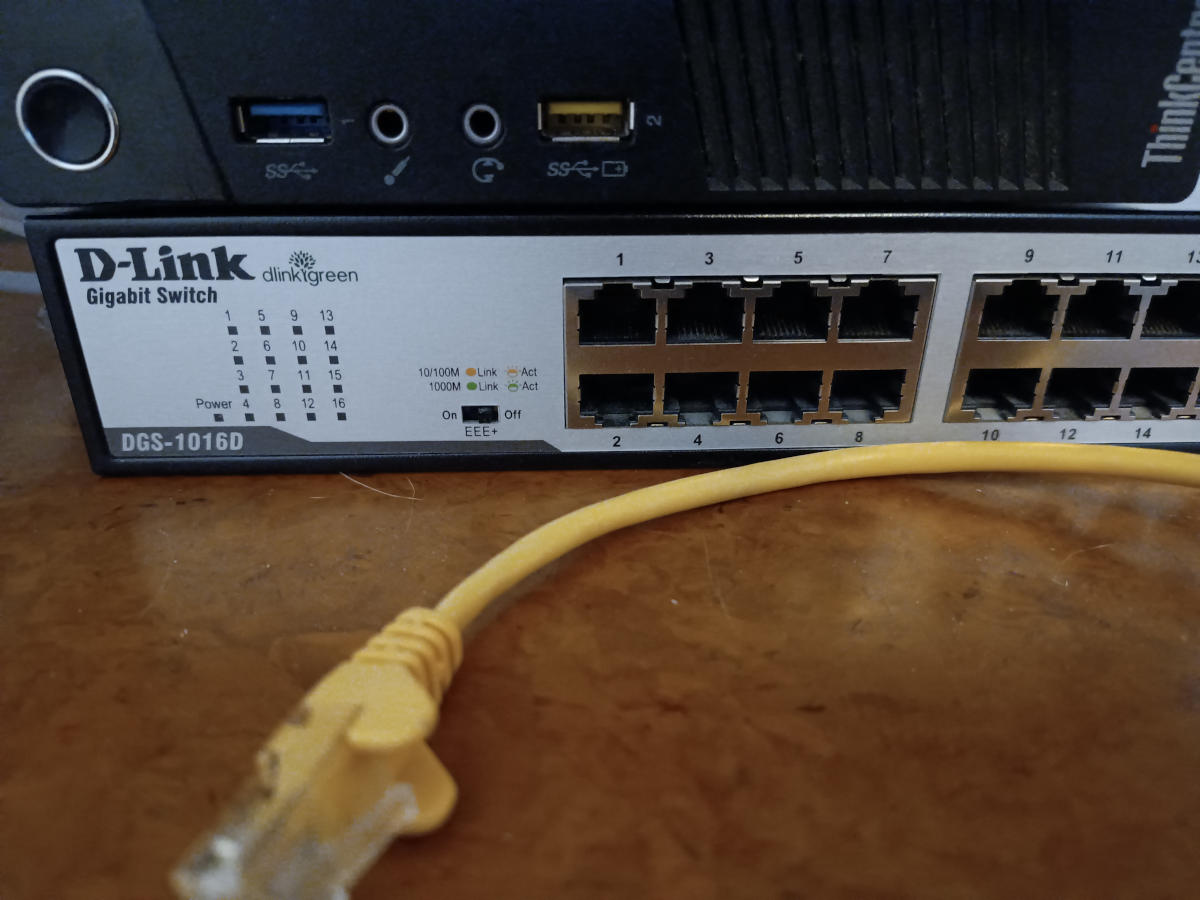
The switch for the cluster network
Next I burned a temporary copy of the Ubuntu 24.04 Desktop installer onto a USB drive (again using Startup Disk Creator) and booted this up - although it’s mostly an installer, you can also use it to “try out” Ubuntu, and I used that option to give me a test environment to make sure things were working as expected - not least that it would actually boot all the way to a working OS!
This, incidentally, is how I discovered initially that I had the ethernet card’s ribbon cable plugged in the wrong way around, but I’ll skip over those details and just show the successful output.
Anyway, booted (temporarily) into Ubuntu, I checked the physical devices with lspci:
$ lspci
00:00.0 Host bridge: Intel Corporation 4th Gen Core Processor DRAM Controller (rev 06)
00:02.0 VGA compatible controller: Intel Corporation 4th Generation Core Processor Family Integrated Graphics Controller (rev 06)
00:03.0 Audio device: Intel Corporation Xeon E3-1200 v3/4th Gen Core Processor HD Audio Controller (rev 06)
00:14.0 USB controller: Intel Corporation 8 Series/C220 Series Chipset Family USB xHCI (rev 04)
00:16.0 Communication controller: Intel Corporation 8 Series/C220 Series Chipset Family MEI Controller #1 (rev 04)
00:19.0 Ethernet controller: Intel Corporation Ethernet Connection I217-V (rev 04)
00:1a.0 USB controller: Intel Corporation 8 Series/C220 Series Chipset Family USB EHCI #2 (rev 04)
00:1b.0 Audio device: Intel Corporation 8 Series/C220 Series Chipset High Definition Audio Controller (rev 04)
00:1c.0 PCI bridge: Intel Corporation 8 Series/C220 Series Chipset Family PCI Express Root Port #1 (rev d4)
00:1c.3 PCI bridge: Intel Corporation 8 Series/C220 Series Chipset Family PCI Express Root Port #4 (rev d4)
00:1d.0 USB controller: Intel Corporation 8 Series/C220 Series Chipset Family USB EHCI #1 (rev 04)
00:1f.0 ISA bridge: Intel Corporation H81 Express LPC Controller (rev 04)
00:1f.2 SATA controller: Intel Corporation 8 Series/C220 Series Chipset Family 6-port SATA Controller 1 [AHCI mode] (rev 04)
00:1f.3 SMBus: Intel Corporation 8 Series/C220 Series Chipset Family SMBus Controller (rev 04)
02:00.0 Ethernet controller: Realtek Semiconductor Co., Ltd. RTL8111/8168/8411 PCI Express Gigabit Ethernet Controller (rev 07)
Nice, two Ethernet devices as expected - and I did verify that removing the mpcie ethernet card caused the second device, by Realtek, to disappear. So the Intel is the onboard chipset and the Realtek is the added device.
Then checking the logical networking devices with ip:
$ ip address
1: lo: <LOOPBACK,UP,LOWER_UP> mtu 65536 qdisc noqueue state UNKNOWN group default qlen 1000
    link/loopback 00:00:00:00:00:00 brd 00:00:00:00:00:00
    inet 127.0.0.1/8 scope host lo
       valid_lft forever preferred_lft forever
    inet6 ::1/128 scope host noprefixroute
       valid_lft forever preferred_lft forever
2: enp2s0: <BROADCAST,MULTICAST,UP,LOWER_UP> mtu 1500 qdisc fq_codel state UP group default qlen 1000
    link/ether 00:e0:4c:68:01:77 brd ff:ff:ff:ff:ff:ff
    inet 192.168.1.157/24 brd 192.168.1.255 scope global dynamic enp2s0
       valid_lft 2631sec preferred_lft 2631sec
    inet6 2001:2042:3750:d500:2e0:4cff:fe68:177/64 scope global dynamic mngtmpaddr
       valid_lft 1170sec preferred_lft 1170sec
    inet6 fe80::2e0:4cff:fe68:177/64 scope link
       valid_lft forever preferred_lft forever
3: eno1: <BROADCAST,MULTICAST> mtu 1500 qdisc noop state DOWN group default qlen 1000
    link/ether 00:23:24:94:35:59 brd ff:ff:ff:ff:ff:ff
    altname enp0s25
Device enp2s0 is wired to my normal switch and through that to the Telia internet
connection. It’s in UP state, has been allocated an IP address of 192.168.1.157 from the Telia router on its
private subnet (the Telia router does NAT to the real internet). The other physical device eno1 is
in DOWN state. All as expected, although originally I intended to use them the other way around (not
that it matters).
If you, like me, were expecting something like eth0 as a device name, then yeah,
they changed all that apparently. So we can see
that enp2s0 is PCIe hardware in PCI slot 2 as card 0. Then device eno1 is the onboard interface at
“firmware index” 1.
At this point a test ping to my laptop on my internal general network…
$ ping -c 1 -w 1 192.168.1.100
PING 192.168.1.100 (192.168.1.100) 56(84) bytes of data.
64 bytes from 192.168.1.100: icmp_seq=1 ttl=64 time=1.48 ms

--- 192.168.1.100 ping statistics ---
1 packets transmitted, 1 received, 0% packet loss, time 0ms
rtt min/avg/max/mdev = 1.476/1.476/1.476/0.000 ms
…and to a machine on the real internet (the Google DNS server)…
$ ping -c 1 -w 1 8.8.8.8
PING 8.8.8.8 (8.8.8.8) 56(84) bytes of data.
64 bytes from 8.8.8.8: icmp_seq=1 ttl=58 time=2.26 ms

--- 8.8.8.8 ping statistics ---
1 packets transmitted, 1 received, 0% packet loss, time 0ms
rtt min/avg/max/mdev = 2.261/2.261/2.261/0.000 ms
…both worked just fine. Yay!
Finally, I tried the Okla speedtest (they have a Linux CLI version of it) and that showed near enough 1 Gbit over the added ethernet connection, so I was pretty confident this was going to work out well as a router.
Next
So, next steps…
Install an OS (Debian) on this machine, configure that second port to host a new subnet, offer DHCP services on it, set up routing and NAT between the two networks, and get started on the basics of PXE network booting one of the client machines. How hard could it be…?
Part 2 - Boot across the network
Footnotes
¹ Reddit posts sometimes get deleted for one reason or another, so here's an archived copy of it that (hopefully) sticks around for longer! https://archive.is/M2g2Q